Spintly ZEON offers a complete solution for users and visitors by blending QR scanning with BLE and NFC access. This ensures easy operation across all levels.
Spintly ZEON offers a complete solution for users and visitors by blending QR scanning with BLE and NFC access. This ensures easy operation across all levels.
INSTALLATION GUIDE :
Spintly ZEON QR
Model No : SQR-021
Spintly ZEON QR offers a complete solution for users and visitors by blending QR / Barcode scanning with BLE and NFC access. This ensures easy operation across all levels.
1. Product Features and Specifications
1.1. Features
Wireless BLE Mesh Networking
Easy to Install and Set-up
QR based access
Cloud-based platform
Smartphone-based access
Card-based access
1.2. Electrical Specifications
Power source: 12V DC Input
Power consumption: 2.4W max at 12V
2. Mechanical Dimensions
3. Mounting Instructions :
Step 1. Pre-drill the mounting locations using Drill Template provided in the box. Then mount the back plate on the wall with the help of wall plugs and screws (ISO #6, 25mmL, PAN+, 2 qty) as shown above.
Step 2. Strip and connect the wires as per the pigtail color code (refer Fig 4.1.1) and connection diagram under Wiring Instructions – Section 4.
Step 3. Once the connection is done, pass the pigtail through the back plate opening.
Step 4. Mount the reader on the back plate (align in the backplate notch) as shown in above image.
Step 5. Secure the reader using M3 x 8mm screws (1 qty) as shown in above image.
4. Wiring Instructions
4.1. Pigtail color code
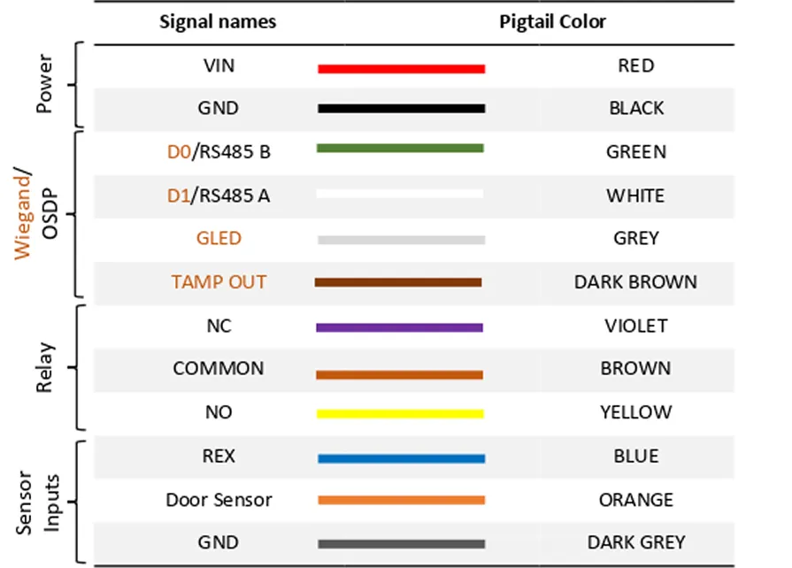
ZEON reader is equipped with a 10 core pigtail required during the connection process. The table below describes the signal names along with their corresponding color code.
Fig 4.1.1
The reader supports various modes of configuration. The connection of wires will differ based on the selected configuration. To ensure proper setup and functionality, refer to the configurations listed below.
5. Configurations
The reader supports various modes of configuration. The connection of wires will differ based on the selected configuration. To ensure proper setup and functionality, refer to the configurations listed below.
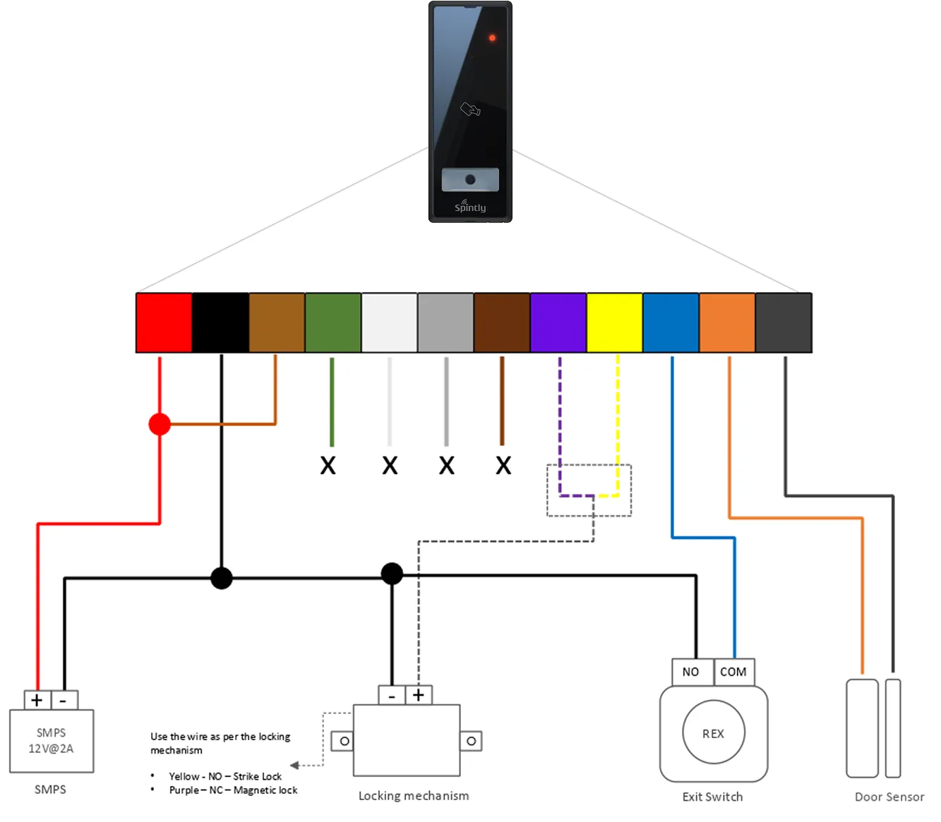
5.1. Configuration 1 : Standalone Spintly Reader
Fig 5.1.1
Short COMMON wire to VIN wire of the Reader Connect the locking mechanism and sensor inputs (Door sensor and REX) to the reader as shown above.
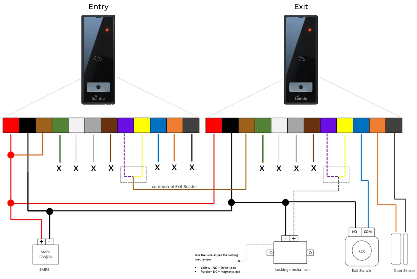
5.2. Configuration 2 : Spintly Entry with Exit reader
Fig 5.2.1
As shown in above diagram,
Both the entry and exit Spintly readers will share the same power lines. Connect together the VIN wires of both the readers. Similarly for GND wires (ground)
Short COMMON wire of Entry Reader to VIN (“A”)
Short NC wire of Entry reader to COMMON wire (“B”) of Exit reader
Connect the locking mechanism (Strike lock or Magnetic lock) to NC (in case of mag lock) wire of Exit Reader
Connect the Door sensor to the Exit reader
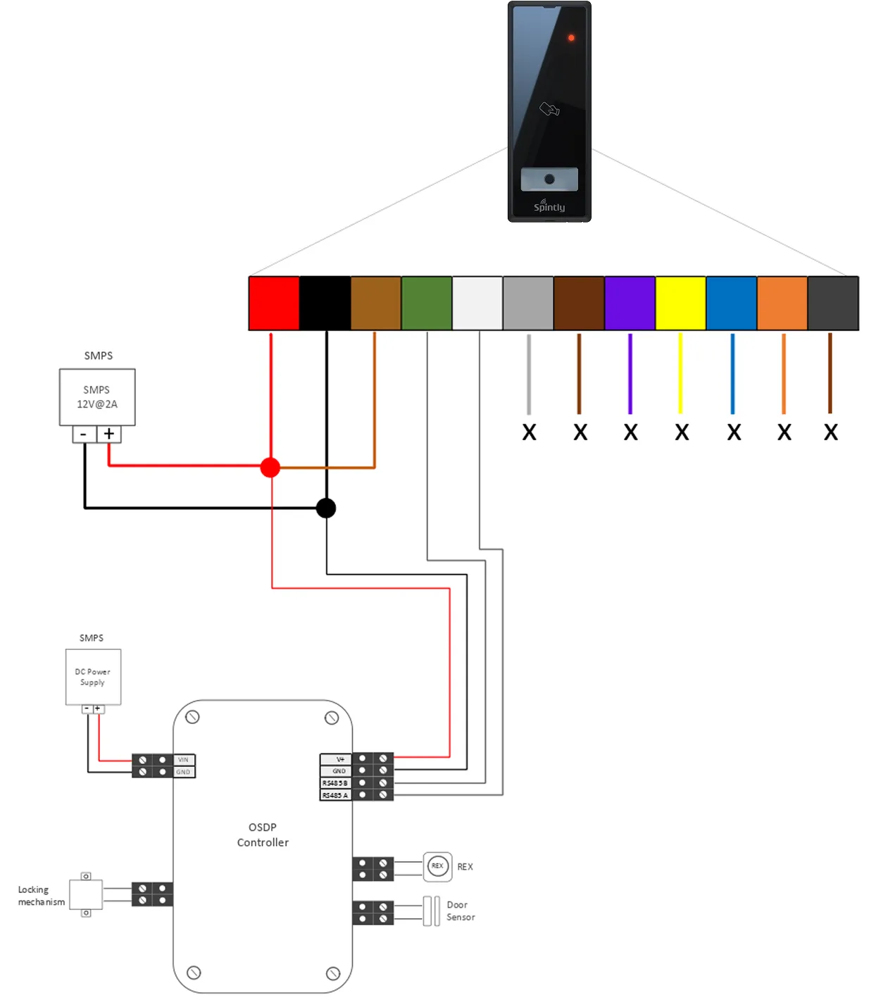
5.3. Configuration 3 : Spintly Reader with OSDP Controller
Fig 5.3.1
As shown in above diagram,
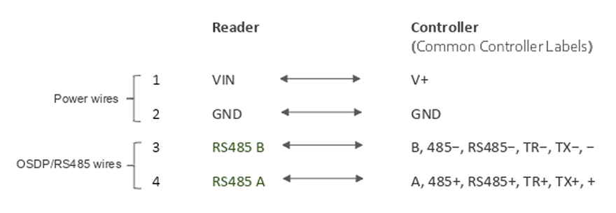
Below mentioned 4 wires should be connected between Reader and Controller
Fig 5.4.1
Note: On controller side, RS485 terminal naming conventions may vary between controller manufacturers. Controller RS485 terminals may be labeled as A/B, 485+/485-, RS485+/RS485-, TR+/TR-, TX+/TX-, or simply +/− If communication is not established after wiring, verify the controller’s RS485 polarity and interchange the RS485 A and RS485 B connections if required.
OSDP Termination (120 Ω):
The reader includes an on-board 120 Ω termination resistor, which can be enabled using the “Termination Jumper (TJ)” accessible on the back side of the reader.
For cable runs longer than 200 ft (61 m) or in environments with high EMI (Electromagnetic Interference), insert the “Termination Jumper” on the PCB header to enable the 120 Ω termination across TR+ / TR–
For shorter cable runs, or when multiple devices are connected on the same RS-485 bus, keep the jumper open unless this device is the last device on the communication line.
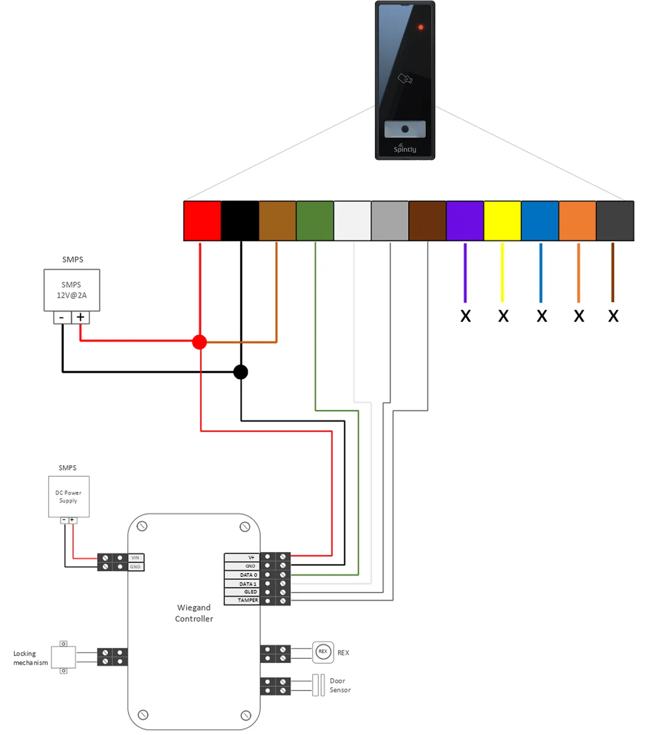
5.4. Configuration 4 : Spintly Reader with Wiegand Controller
Fig 5.5.1
As shown in above diagram,
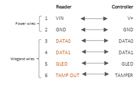
Below mentioned 6 wires should be connected between Reader and Controller.
Fig 5.6.1
Connect the locking mechanism and sensor inputs (Door sensor and REX) to the controller.