Spintly UNO-WO Reader with it’s elegant design provides seamless user experience that allows users to unlock doors with their smartphones.
Spintly UNO-WO Reader with it’s elegant design provides seamless user experience that allows users to unlock doors with their smartphones.
1. Product Features and Specifications
1.1. Features
BLE Mesh connectivity to Gateway
Wide Input operating voltage range
Retrofit with legacy controllers over Wiegand or OSDP
Tamper detection
Cloud based access management
Adjustable operational distance for Mobile credential access
Over-the-air firmware update support
1.2. Electrical Specifications
Power source: 12V/24V DC Input
Power consumption: 2.4W max at 12V
2. Mechanical Dimensions
Length = 90 mm
Width = 49.5 mm
Depth = 29 mm
Length = 90 mm
Width = 49.5 mm
Depth = 29 mm
3. Mounting Instructions :
Step 1. Pre-drill the mounting locations using Drill Template provided in the box. Then mount the back plate on the wall with the help of wall plugs and screws (4 qty) as shown above.
Step 2. Before proceeding with wiring, toggle the Interface Switch to either W (Wiegand) or O (OSDP) position based on the selected configuration (Refer Wiring Instructions – section 4. Applicable to configuration 3 or 4 based on the switch position)
Step 3. Strip and connect the wires as per the pigtail color code (refer Fig 4.1.1) and connection diagram (refer Fig 4.2.1) under Wiring Instructions – Section 4.
Step 4. Once the connection is done, pass the pigtail through the back plate opening
Step 5. Mount the reader on the back plate and secure it using M3 x 8mm screws (2qty)
4. Wiring Instructions :
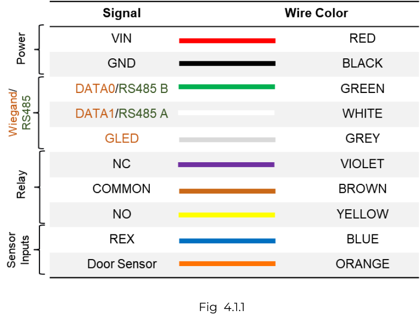
4.1. Pigtail color code
UNO-WO reader is equipped with a 10 core pigtail required during the connection process. The table below describes the signal names along with their corresponding color code.
The reader supports various modes of configuration. The connection of wires will differ based on the selected configuration. To ensure proper setup and functionality, refer to the configurations listed below.
In this mode, both the entry and exit Spintly readers will share the same power lines. Connect together the VIN wires of both the readers. Similarly, for GND wires (ground)
Connect OSDP wires – Green and White to respective wires of exit reader (as shown in above Fig 4.3.1)
Short VIN wire to COMMON wire of Exit Reader
Connect the locking mechanism (Strike lock or Magnetic lock) to NC (in case of mag lock) wire of Exit Reader
The Door sensor should be connected to Exit reader
4.4. Configuration 3 : Spintly Reader with OSDP Controller
Make sure the interface switch on reader is toggled to “O” (OSDP) position as instructed previously. Refer to section 3 – step 2. (for Model No : SU-016)
Below mentioned 4 wires should be connected from Reader to the respective terminal of Controller:
Power wires — VIN and GND
Communication wires — Connect RS485 A and RS485 B (refer the color code shown in the above table) to the A and B terminal of the controller respectively. Refer controller manual for more details.
Connect the locking mechanism and sensor inputs (Door sensor and REX) to controller
4.5. Configuration 4 : Spintly Reader with Wiegand Controller
Make sure the interface switch is toggled to “W” (Wiegand) position as instructed previously. Refer to section 3 – step 2. (for Model No : SU-016)
Below mentioned 5 wires should be connected from Reader to the respective terminal of Wiegand controller:
Power wires — VIN and GND
Communication wires — DATA0 (D0), DATA1 (D1), and GLED (refer the color code shown in above table) to the respective terminals of Wiegand controller.
Connect the locking mechanism and sensor inputs (Door sensor and REX) to controller