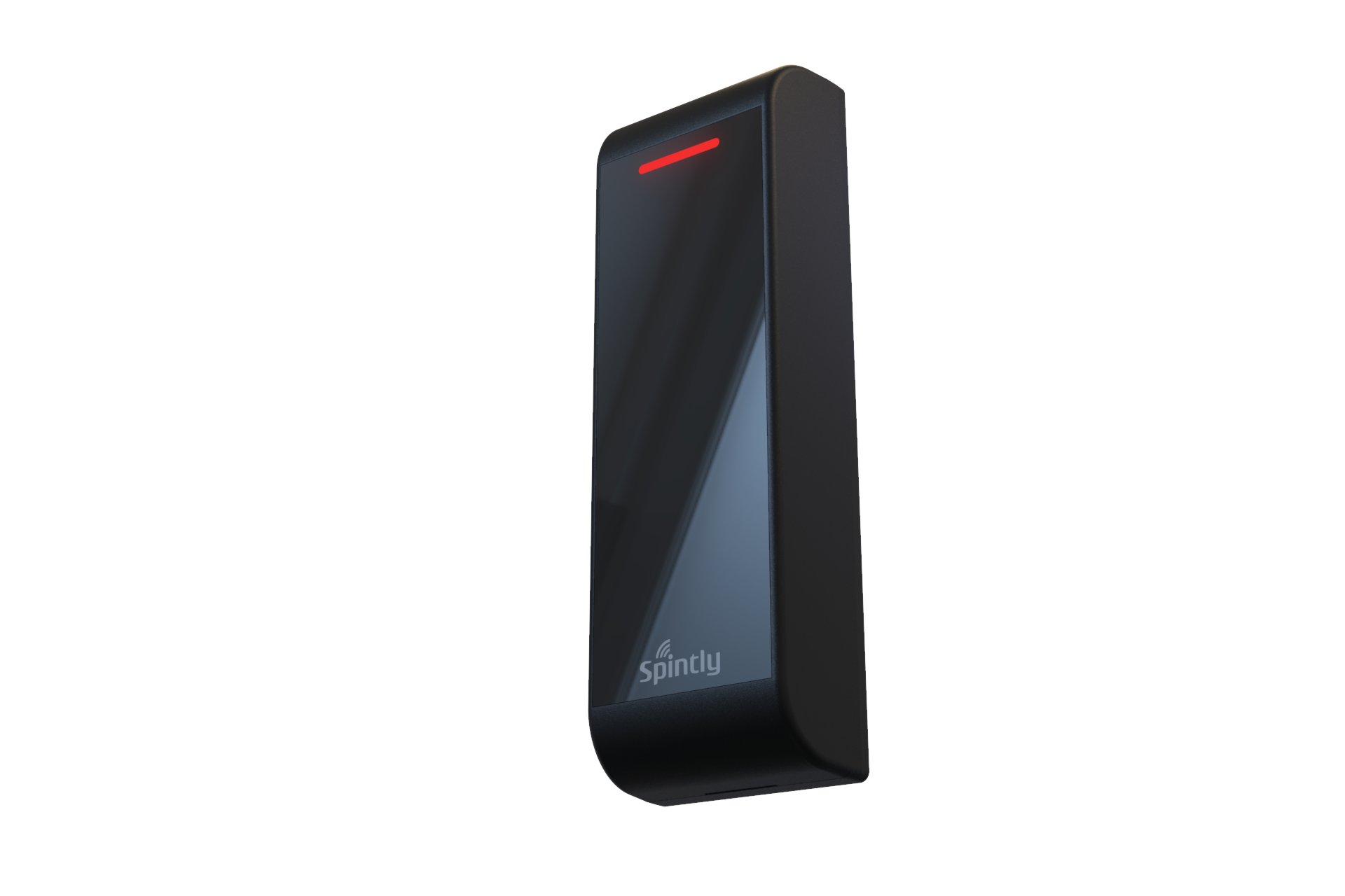
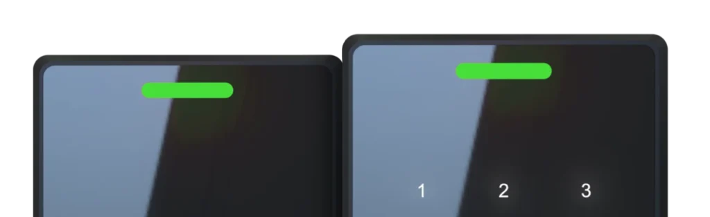
Spintly KREO is an advanced access control reader with the highest level of security and reliability, with IP-65 rating for ruggedness. It offers seamless door unlocking using BLE, NFC and a Keypad
Spintly KREO is an advanced access control reader with the highest level of security and reliability, with IP-65 rating for ruggedness. It offers seamless door unlocking using BLE, NFC and a Keypad
1. Product Features and Specifications
1.1. Features
Wireless BLE Mesh Networking
Easy to Install and Set-up
IP65 Rated
Cloud based platform
Smartphone based access
Card based access – HF and LF cards
1.2. Electrical Specifications
Power source: 12V/24V DC Input
Power consumption: 2.4W max at 12V
2. Mechanical Dimensions
3. Mounting Instructions :
Step 1. Mark and Drill Mounting Holes Pre-drill the mounting locations using Drill Template provided in the box.
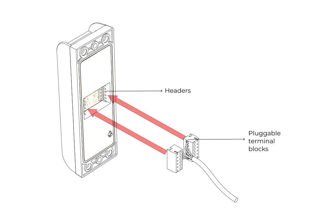
Step 2. Wiring Strip and connect the wires to the pluggable terminal block provided in the box according to the required configuration (configuration 1, 2, 3 or 4). Plug the terminal block into the headers located on the back side of the reader.
Note : Ensure that the terminal blocks are plugged into the correct side and orientation.
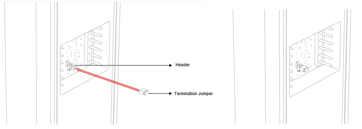
Step 3. Insert Termination Jumper (Applicable for OSDP Configuration Only) Insert the “Termination jumper” on the header provided on the back side PCB (refer below image).
This step is applicable only for “Configuration 3 : Spintly Reader with OSDP Controller” (section 5.3). Please refer to the detailed criteria mentioned in the configuration section before enabling termination.
Step 4. Mount the reader Mount the reader onto the wall using the provided wall plugs and screws (ISO #6, 25mmL, PAN+, 2 qty)
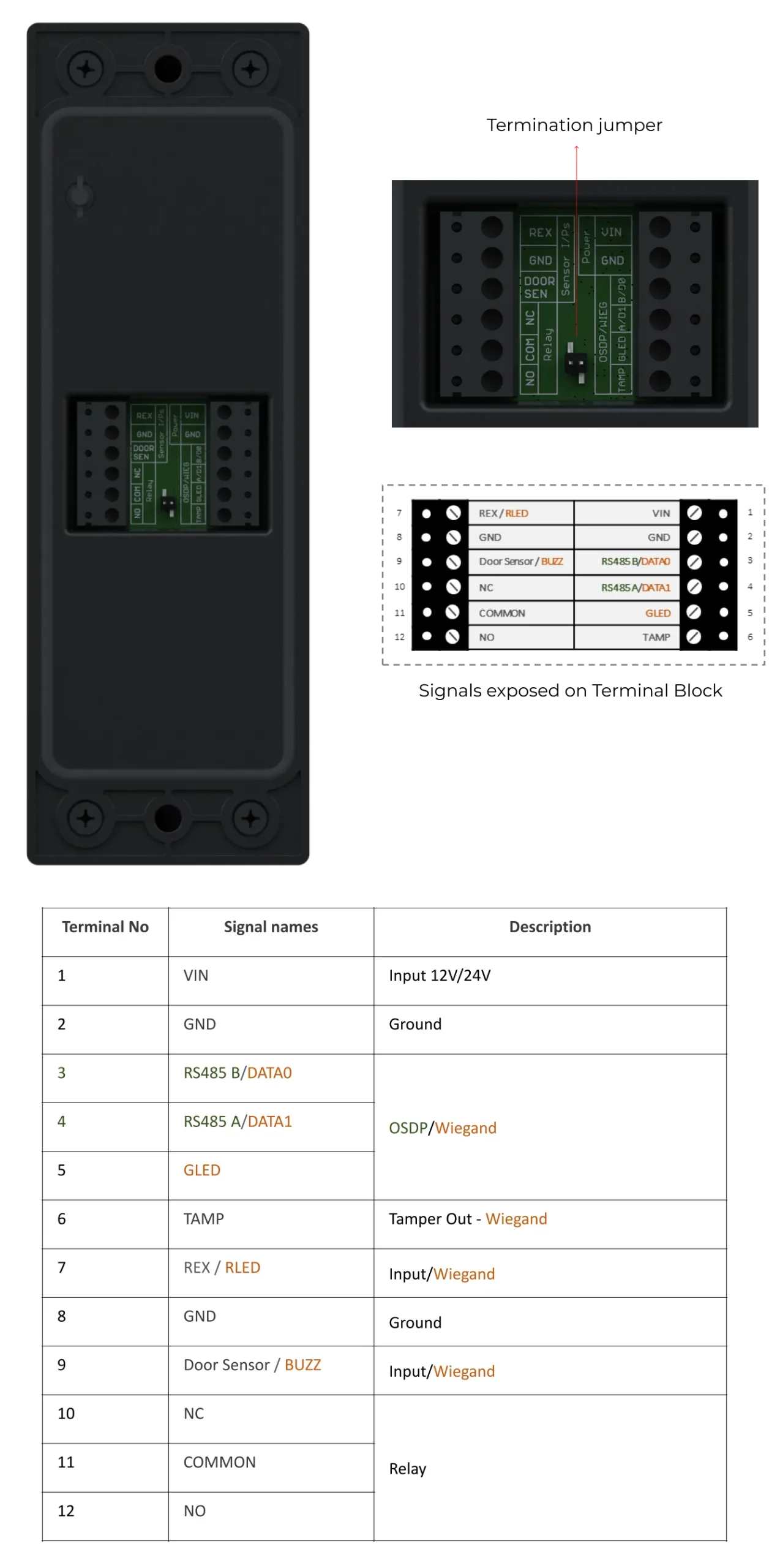
4. Terminal Block Pinout
Spintly KREO features an exposed terminal block on its backside, providing easy access to all required signals during installation. This simplifies the installation process by allowing straightforward connection of wiring without the need for additional steps
5. Configurations
The reader supports various modes of configuration. The connection of wires will differ based on the selected configuration. To ensure proper setup and functionality, refer to the configurations listed below.
5.1. Configuration 1 : Standalone Spintly Reader
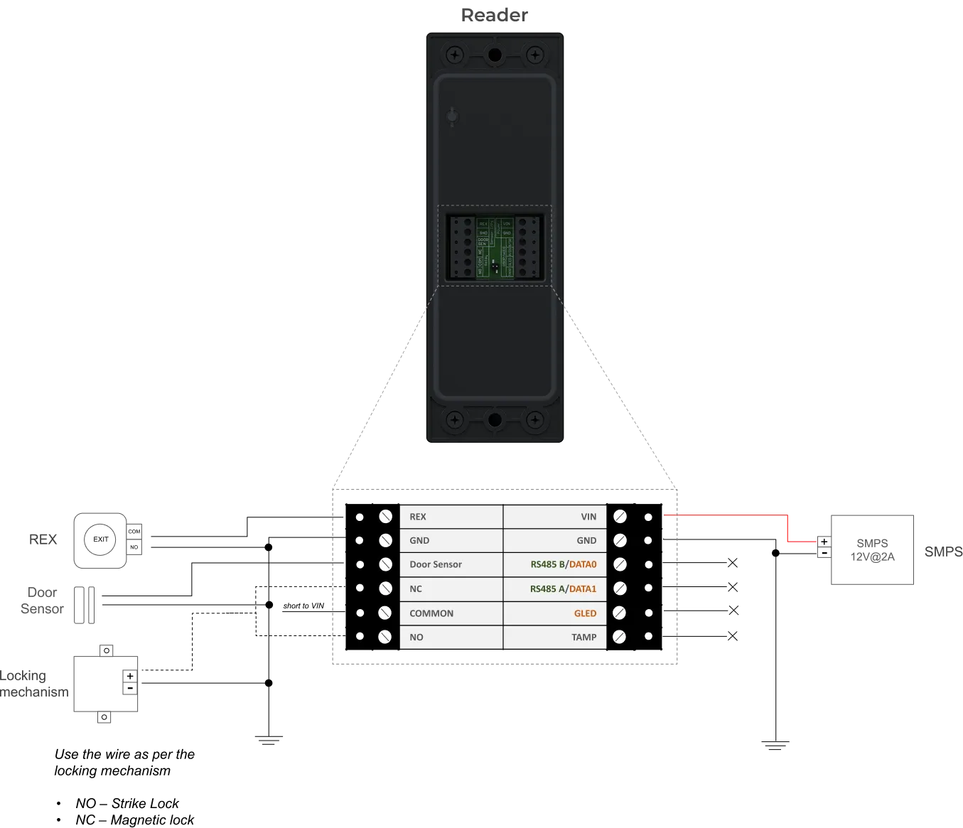
Short COMMON wire to VIN wire of the Reader
Connect the locking mechanism and sensor inputs (Door sensor and REX) to the reader as shown above
5.2. Configuration 2 : Spintly Entry with Exit reader
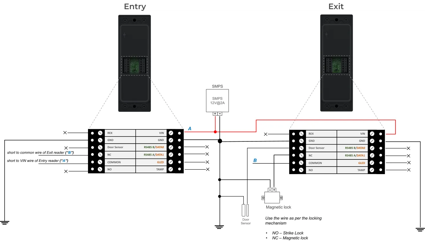
As shown in above diagram,
Both the entry and exit Spintly readers will share the same power lines. Connect together the VIN wires of both the readers. Similarly for GND wires (ground)
Short COMMON wire of Entry Reader to VIN (“A”)
Short NC wire of Entry reader to COMMON wire (“B”) of Exit reader
Connect the locking mechanism (Strike lock or Magnetic lock) to NC (in case of mag lock) wire of Exit Reader
Connect the Door sensor to the Exit reader
5.3. Configuration 3 : Spintly Reader with OSDP Controller
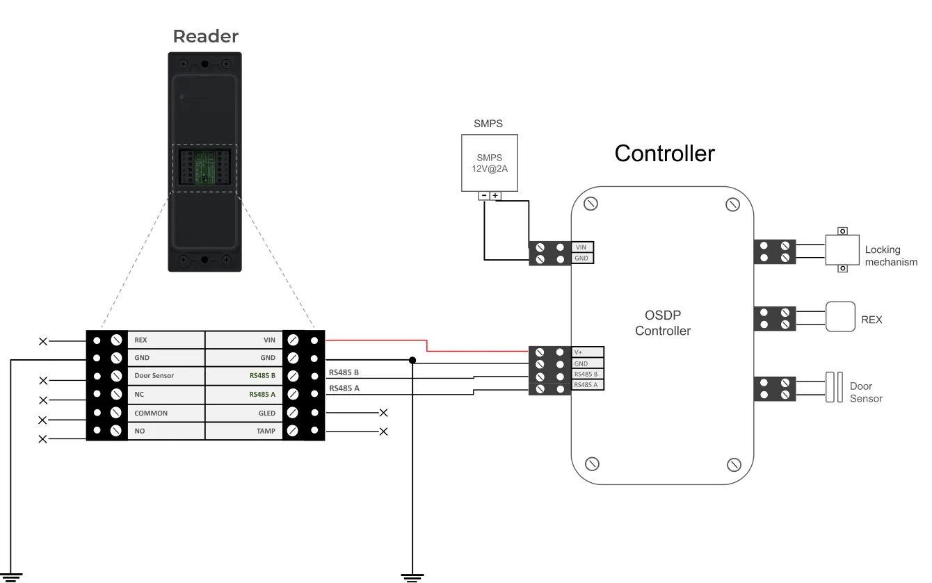
As shown in above diagram,
Below mentioned 4 wires should be connected from Reader and Controller
Connect the locking mechanism and sensor inputs (Door sensor and REX) to the controller
OSDP Termination (120 Ω):
The reader includes an on-board 120 Ω termination resistor, which can be enabled using the “Termination Jumper (TJ)” accessible on the back side of the reader.
For cable runs longer than 200 ft (61 m) or in environments with high EMI (Electromagnetic Interference), insert the “Termination Jumper” on the PCB header to enable the 120 Ω termination across TR+ / TR–
For shorter cable runs, or when multiple devices are connected on the same RS-485 bus, keep the jumper open unless this device is the last device on the communication line.
5.4. Configuration 4 : Spintly Reader with Wiegand Controller
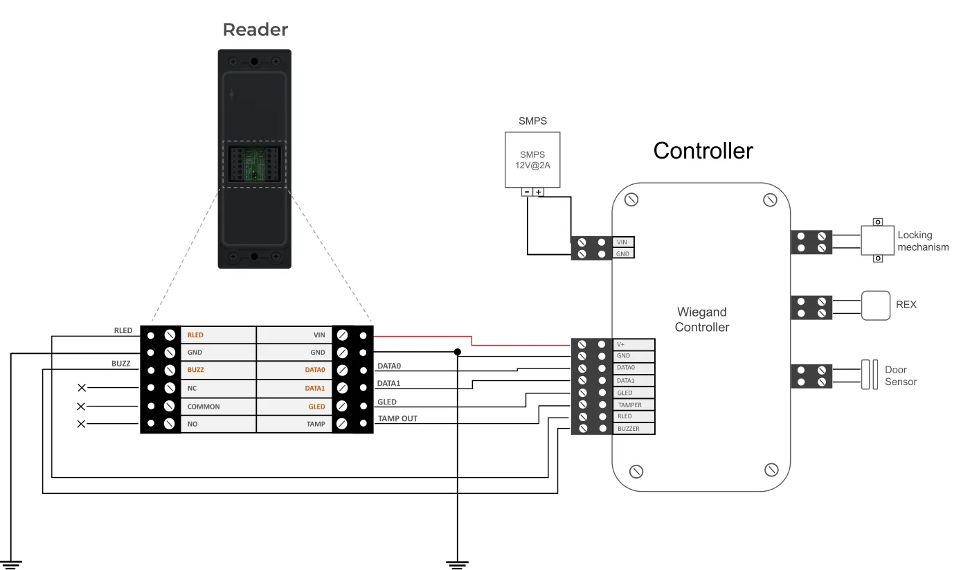
As shown in above diagram,
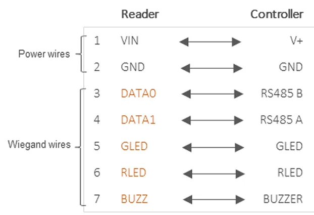
Below mentioned 7 wires should be connected between Reader and Controller
Connect the locking mechanism and sensor inputs (Door sensor and REX) to the controller