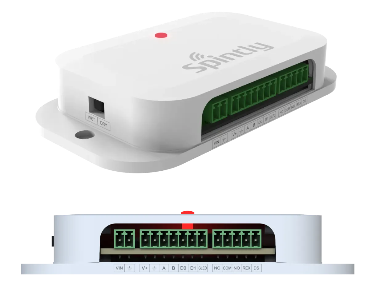
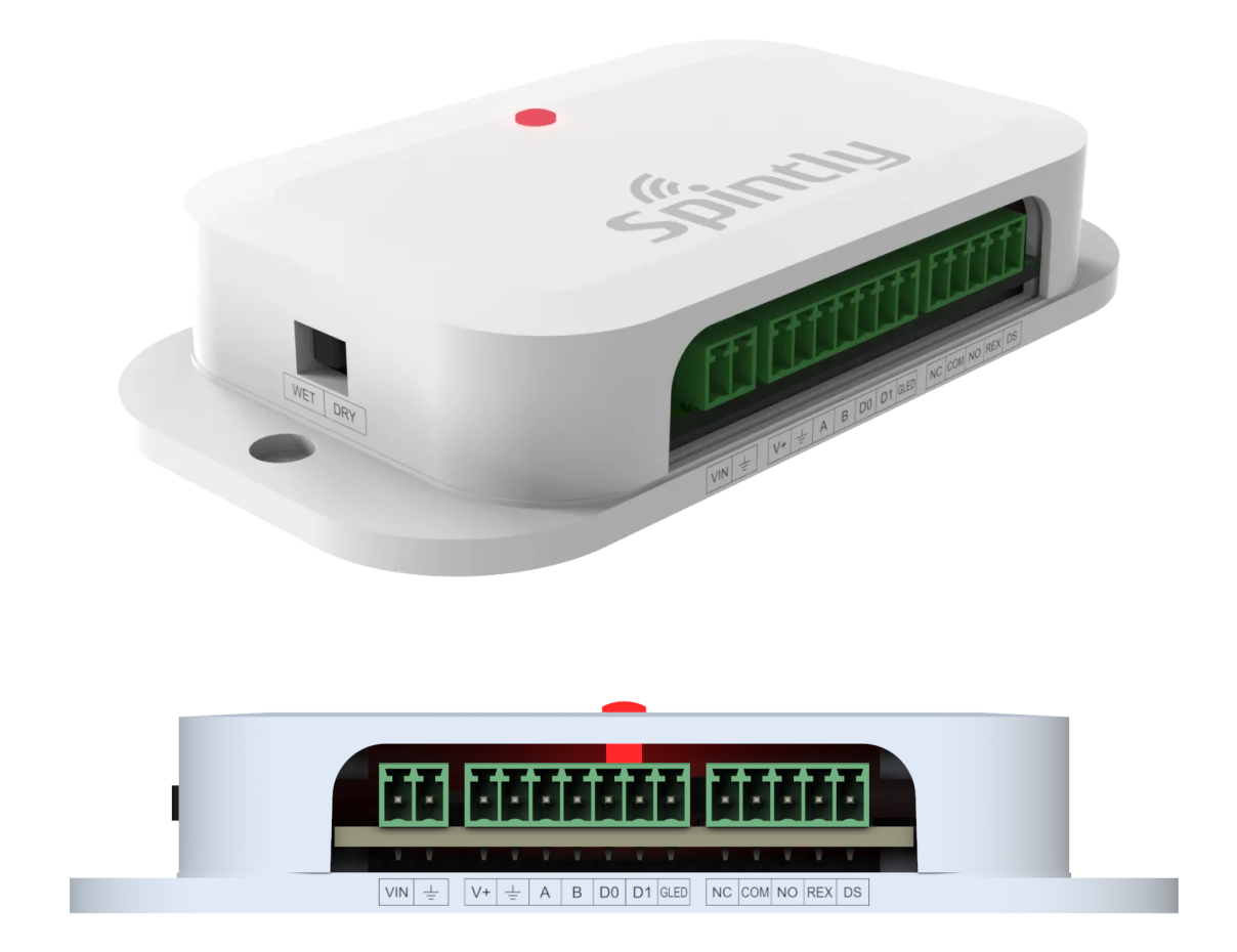
NUOS-1 is a single door controller. It has native OSDP/Wiegand support which provides the highest level of security and reliability. It is designed to be mounted on the secured side of a door, and configurable to make all access control decisions.
NUOS-1 is a single door controller. It has native OSDP/Wiegand support which provides the highest level of security and reliability. It is designed to be mounted on the secured side of a door, and configurable to make all access control decisions.
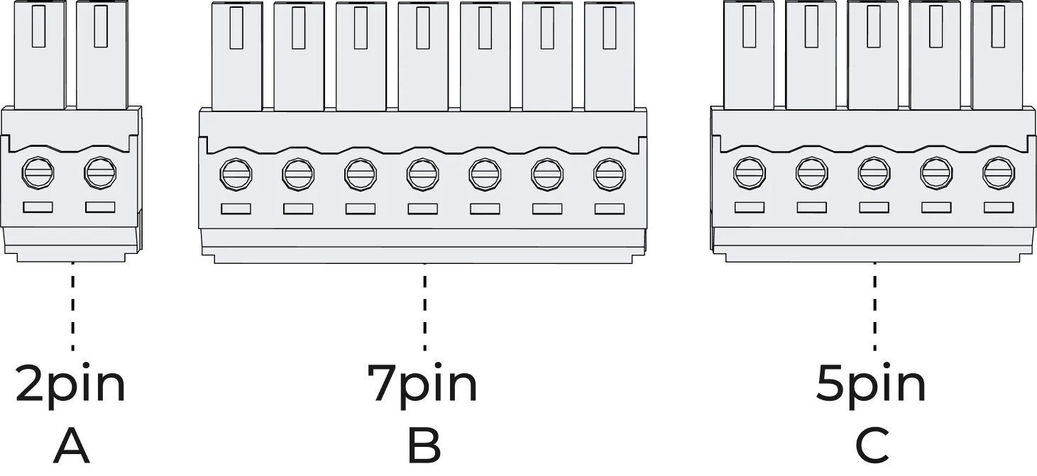
Step 1. Pick out the connectors (2pin-A, 7pin-B, 5pin-C) provided in the box as shown in below image
Fig 3.1
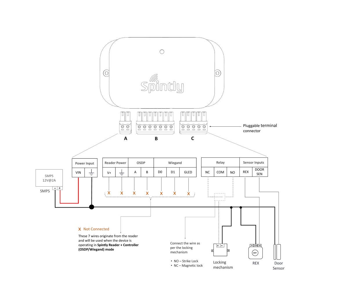
Step 2. Connection diagram and Wiring: It can support 2 modes of configuration. The connection of wires will differ based on the selected configuration.
• Configuration 1 : Standalone Spintly Controller
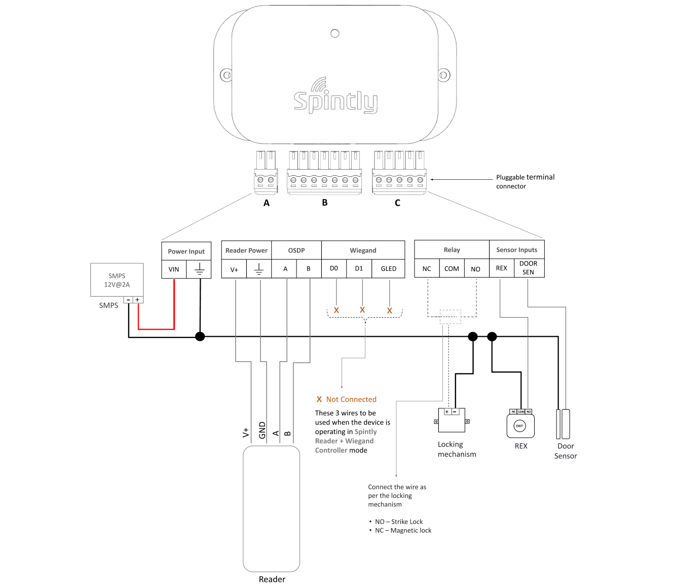
To ensure proper setup, follow the connection diagram (Fig 3.2 below) and screw in the wires into A, B, C (using screw driver provided in box) Note : Observe the orientation of A, B and C while screwing in the wires. The screw terminal should be facing the user (refer below image)
Fig 3.2
• Configuration 2 : Spintly Reader with OSDP controller
Fig 3.3
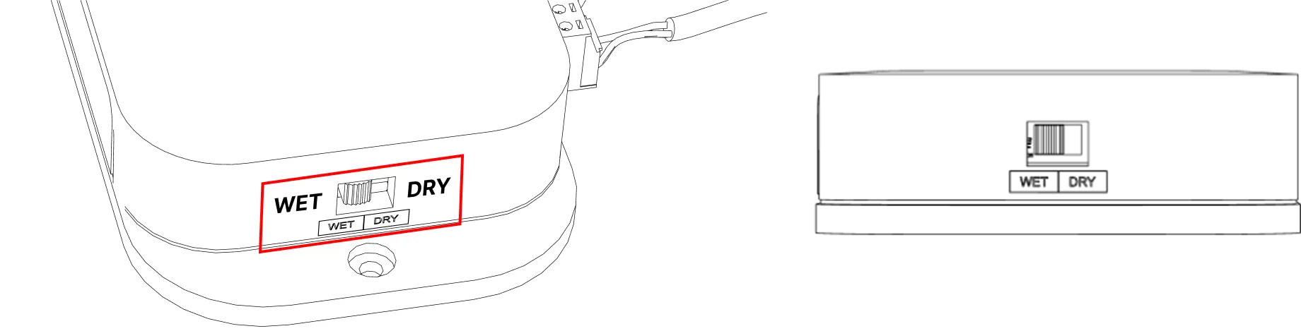
Controller Side – Toggle the switch to WET position to enable lock power on the common terminal of relay (refer Fig 3.3)
Reader Side – The below mentioned 4 signals needs to be connected between Reader and the OSDP controller (refer Fig 3.4)
Power wires – Connect V+ and GND (pluggable connector A)
Communication wires – Connect A and B lines of the reader to the respective A and B (OSDP) lines on the controller side (pluggable connector B)
Refer reader manual for more details.
The locking mechanism (Strike lock or Magnetic lock) should be connected to the Controller (pluggable connector C)
The sensor inputs (REX and Door sensor) should be connected to the controller (pluggable connector C)
Fig 3.4
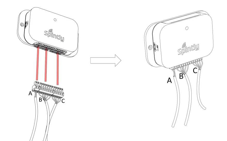
Step 3. Plug in the pluggable connectors A, B and C into its respective mating part on NUOS-1 as shown in the below image (refer Fig 3.5)
Fig 3.5
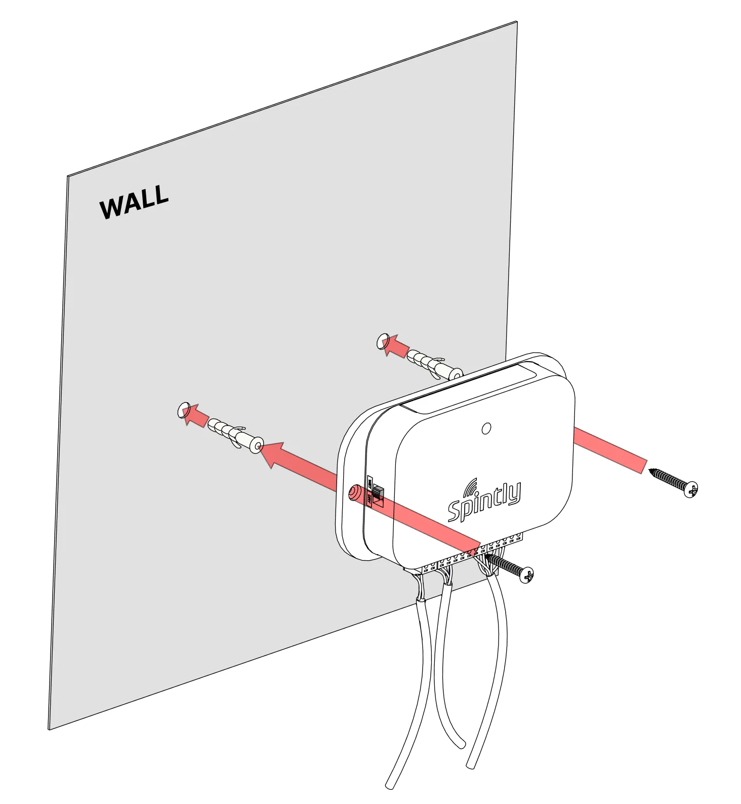
Step 4. Mounting of device on wall
Pre-drill the mounting locations using “Drill Template” provided in the box. Mount the NUOS-1 on the wall using provided wall plugs and screws (2 qty) (refer Fig 3.6)