Spintly HALO – the fingerprint access control reader is designed for the highest standards of security and reliability. It offers seamless door unlocking using fingerprints, smartphones, or NFC cards, ensuring a reliable and enhanced user experience.
Spintly HALO – the fingerprint access control reader is designed for the highest standards of security and reliability. It offers seamless door unlocking using fingerprints, smartphones, or NFC cards, ensuring a reliable and enhanced user experience.
1. Product Features and Specifications
1.1. Features
Wireless BLE Mesh Networking
Easy to Install and Set-up
Fingerprint based access
Fast Identification speed
Cloud based platform
Smartphone based access
Card based access
1.2. Electrical Specifications
Power source: 12V/24V DC Input
Power consumption: 2.4W max at 12V
2. Mechanical Dimensions
Length = 195 mm
Width = 55 mm
Depth = 51 mm
3. Mounting Instructions :
Step 1. Pre-drill the mounting locations using Drill Template provided in the box. Then mount the unit on the wall with the help of wall plugs (3 qty) and mounting screws (3 qty) as shown above.
Step 2. Strip and connect the wires as per the pigtail color code (fig 4.1.1) and connection diagram (refer Fig 4.2.1) under Wiring Instructions- section 4
Step 3. Snap in the front face plate as shown in above image
4. Wiring Instructions :
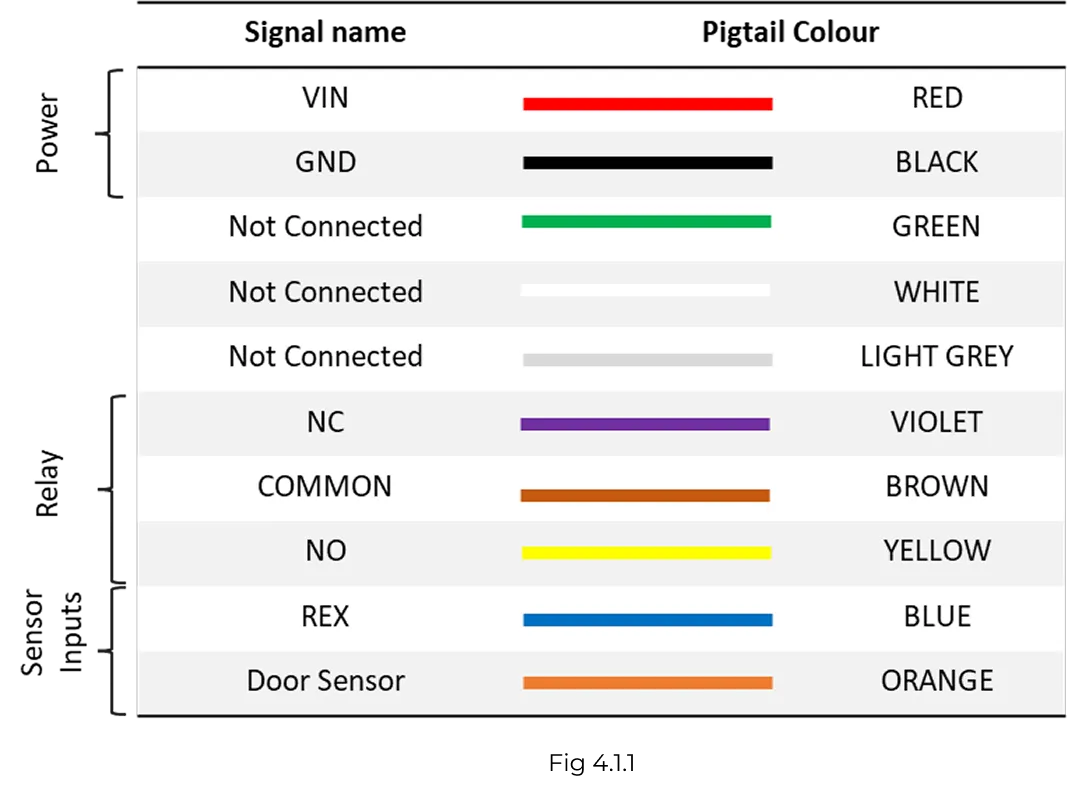
4.1. Pigtail color code
HALO reader is equipped with a 10 core pigtail required during the wiring process. The table below describes the signal names along with their corresponding color code.
The reader supports various modes of configuration. The connection of wires will differ based on the selected configuration. To ensure proper setup and functionality, refer to the configurations listed below.
In this mode, both the entry and exit Spintly readers will share the same power lines. Connect together the VIN wires of both the readers. Similarly, for GND wires (ground).
Short VIN wire to COMMON wire of Entry Reader
Short NC (in case of mag lock) wire of Entry Reader to COMMON wire of Exit Reader
Connect the locking mechanism to NC (in case of mag lock) wire of Exit Reader
The sensor inputs:
Door Sensor – To enable DOTL, please connect the door sensor to the Entry Reader (as shown in above Fig 4.3.1)
Door break-in feature is not available under this configuration.