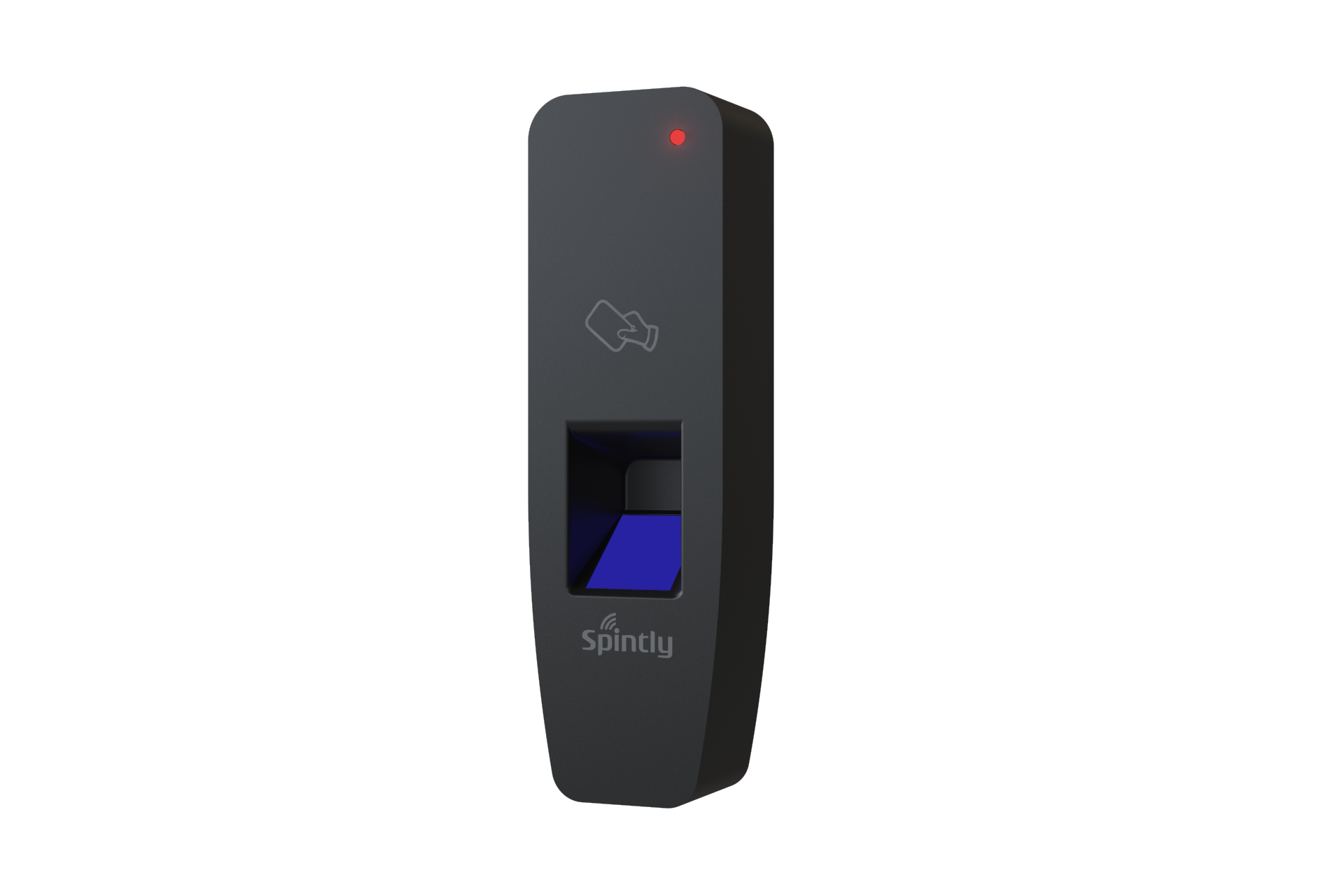
Spintly 3-in-1 access control with its elegant design provides a Flexible Modular and Scalable approach to upgrade your regular doors to smart doors. A smart efficient Fingerprint, Smartphone and NFC cards based solution to manage your access.
Spintly 3-in-1 access control with its elegant design provides a Flexible Modular and Scalable approach to upgrade your regular doors to smart doors. A smart efficient Fingerprint, Smartphone and NFC cards based solution to manage your access.
1. Product Features and Specifications
1.1. Features
Wireless BLE Mesh Networking
Easy to Install and Set-up
Fingerprint based access
Fast Identification speed
Cloud based platform
Smartphone based access
Card based access
1.2. Electrical Specifications
Power source: 12V/24V DC Input
Power consumption: 2.4W max at 12V
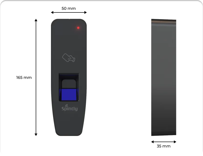
2. Mechanical Dimensions
Fig. 2.1
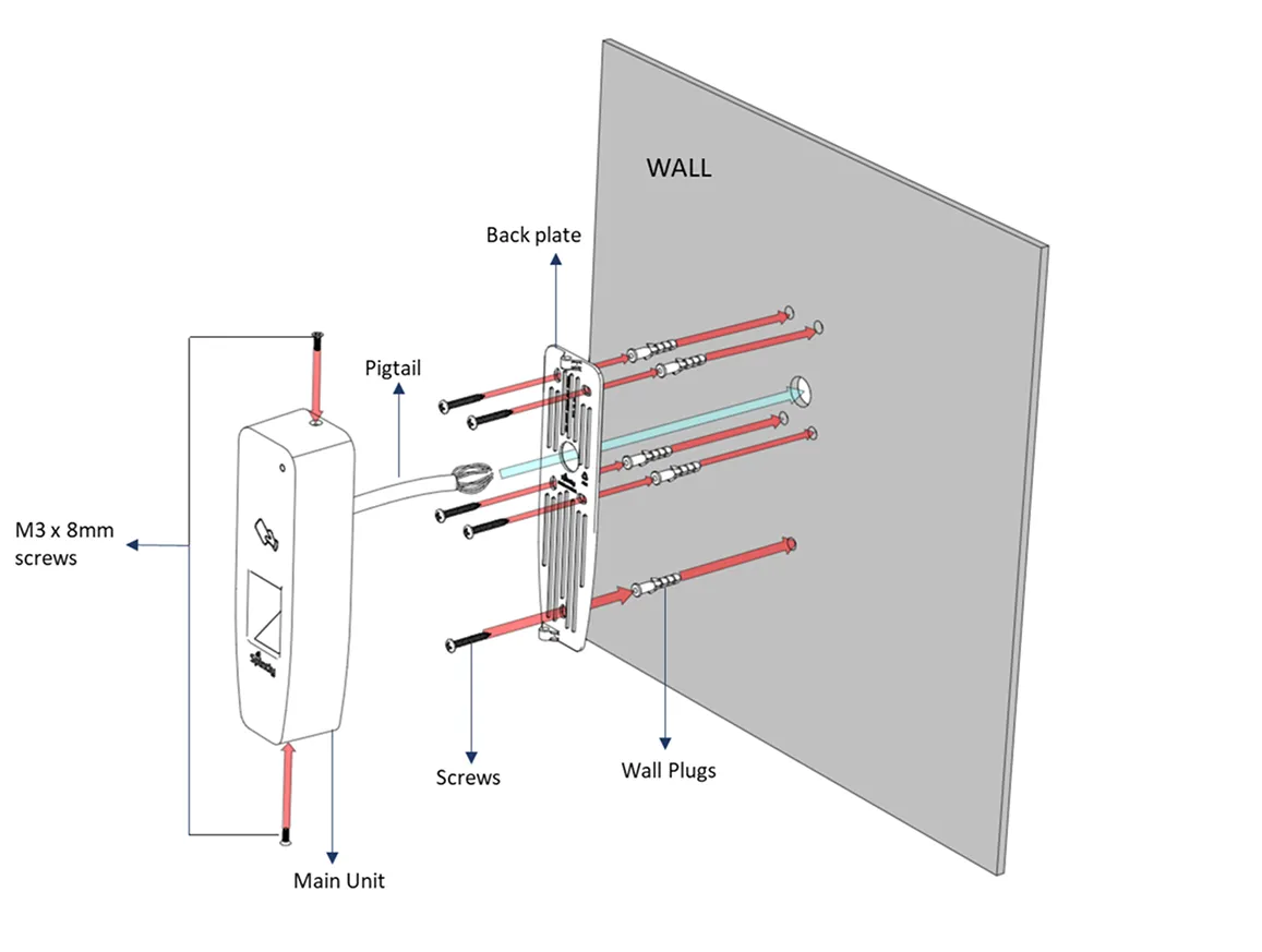
3. Mounting Instructions :
Fig. 3.1
Step 1. Pre-drill the mounting locations using Drill Template provided in the box.
Step 2. Insert the wall plugs (5 Qty) and secure the back plate using the screws provided(5 Qty)
Step 3. Strip and connect the wires as per the pigtail color code and connection diagram. Refer Fig 4.2 under Wiring Instructions.
Step 4. Install the main unit using M3x8mm screws(2 qty)
4. Wiring Instructions
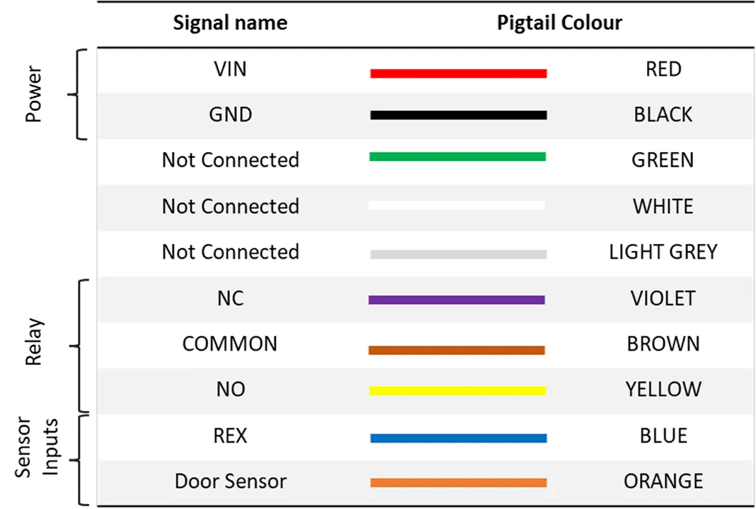
4.1. Pigtail color code
3-in-1 reader is equipped with a 10 core pigtail required during the wiring process. The table below describes the signal names along with their corresponding color code.
Fig. 4.1.1
The reader supports various modes of configuration. The connection of wires will differ based on the selected configuration. To ensure proper setup and functionality, refer to the configurations listed below.
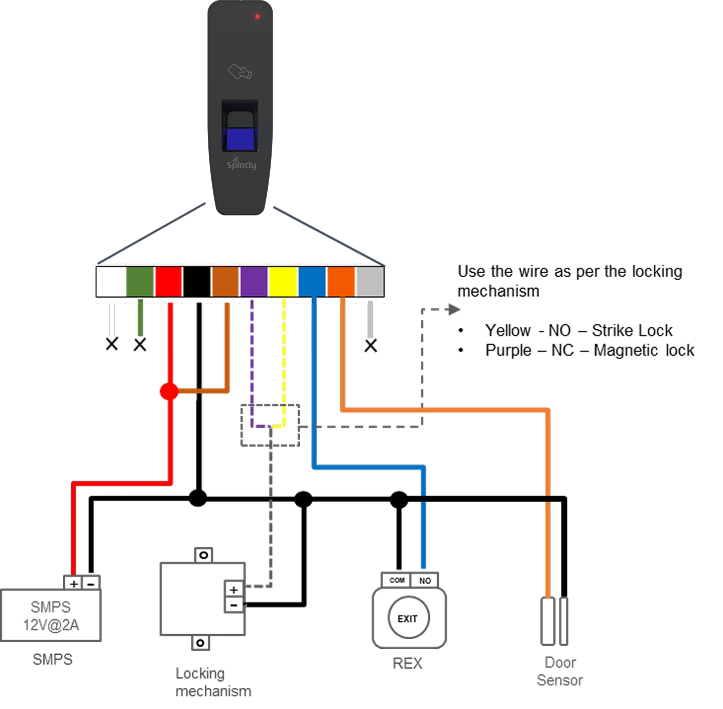
4.2. Configuration 1 : Standalone Spintly Reader
Fig. 4.2.1
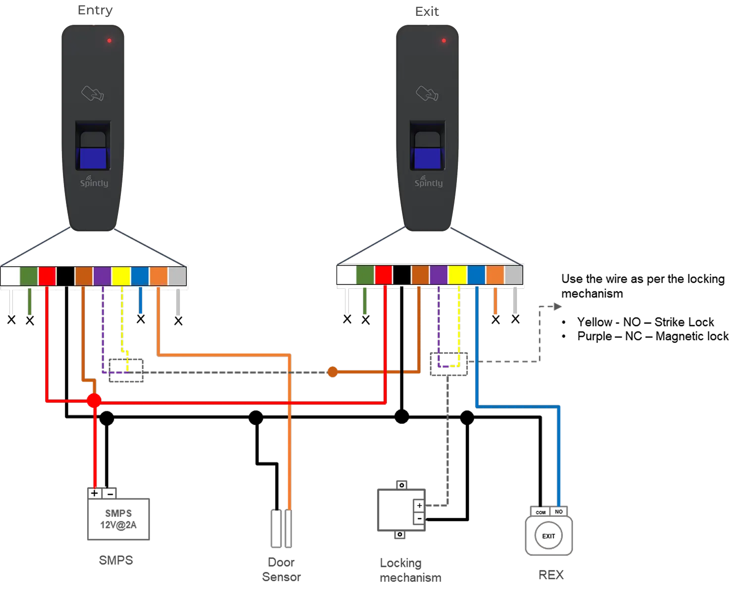
4.3. Configuration 2 : Spintly Entry with Exit reader
Fig. 4.3.1
In this mode, both the entry and exit Spintly readers will share the same power lines. Connect together the VIN wires of both the readers. Similarly for GND wires (ground).
Short VIN wire to COMMON wire of Entry Reader
Short NC (in case of mag lock) wire of Entry Reader to COMMON wire of Exit Reader
Connect the locking mechanism (Strike lock or Magnetic lock) to NC (in case of mag lock) wire of Exit Reader
The sensor inputs,
REX should be connected to Exit reader
Door Sensor – To enable DOTL, please connect the door sensor to the Entry Reader (as sown in above Fig 4.3.1)
Door break-in feature is not available under this configuration.